

|
Courtesy of Shu-he Wei and Liao-jun Zhang, College of Water Conservancy and Hydropower Engineering, Hohai University, Nanjing 210098, P.R. China |
|
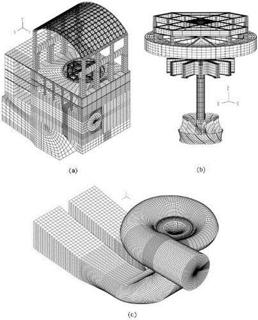
Hydroelectric power plants are used for economic and environmentally friendly electric power generation all around the world. One of the technical challenges in the design FEA / CFD analysis of such structures is to consider the fluid-structure interaction effects. For example, when the water pressure fluctuates as it passes through the fluid passage and the hydraulic turbine, it creates a pulsatile loading that causes vibration of the powerhouse structure. In this example, we see some results of a study dealing with the vibrations of a powerhouse structure due to the fluid-structure interaction, obtained using ADINA FEA / CFD / FSI. We see the ADINA FEA model of the coupled system. The nonlinear transient response of the coupled system was solved using 3000 implicit integration time steps, with a time step of 0.002 seconds (see Ref below). The ADINA CFD fluid was modeled as a Navier-Stokes fluid. The turbulent behavior of the fluid was modeled using the shear stress transport (SST) model. The sliding mesh boundary condition was used to incorporate the large rotations of the turbine blades. |
|
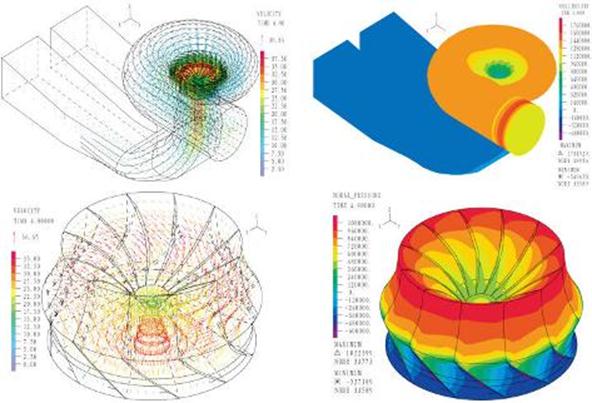
The CFD movie above shows the contour plot of the pressure in the fluid. |
|
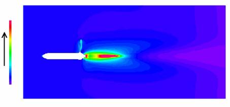
The CFD plots on the left show velocity vector and pressure contour plots in the fluid model at the time = 4.80 s. |
|
The plots above show the Finite element mesh of the: (a) powerhouse structure (FEA) (b) turbine (FEA) (c) fluid (CFD) |
|
Reference S. Wei, L. Zhang, "Vibration analysis of hydropower house based on fluid-structure coupling numerical method"”,Water Science and Engineering, 3(1): 75-84, 2010 |
|
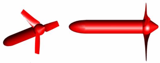
Much effort is being made to develop efficient and cost-effective renewable energy solutions (see Ref.). In conventional hydropower, as well as in the more recent quest to harness the energy from waves and tides, well designed turbomachinery is essential. We feature the ADINA FEA / CFD / FSI analysis of a new hydraulic turbine design to power a generator providing between 1.0 and 1.2 kW for remote dwellings not connected to an electrical supply grid. The analysis was performed by SIM&TEC S.A. using ADINA FEA / CFD / FSI. In the analysis, the turbine was modeled to determine its characteristic curves of torque and power vs. rotational speed. The figures are provided to give an idea of the general trend of the results, but do not include numerical data due to client confidentiality requirements. The movie above shows the calculated flow through the rotating turbine. Figure 1 shows the geometry of the turbine. The finite element mesh used is shown in Figures 2 and 3. |
|
Fig 1 |
|
Fig 2 |
|
Fig 3 |
|
In the ADINA CFD fluid model, a rotating mesh (shown in red in Figure 2) attached to the blades was defined and a separate fixed mesh (green in Figure 2) was also defined, with a sliding surface between these two meshes. The rotating turbine is shown in the movie on the left.
Band plots from the analysis results are shown in Figures 4 and 5. |
|
Reference · C. Deilmann & K.J. Bathe, "A holistic method to design an optimized energy scenario and quantitatively evaluate promising technologies for implementation", International Journal of Green Energy, 6:1-21, 2009.
Courtesy of SIM&TEC S.A. |
|
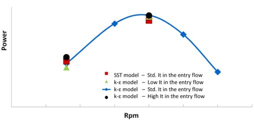
To investigate the effect of river flow turbulence on the results, different values of free flow turbulence intensity (It) were considered. The numerical results were obtained modeling the flow with two different turbulence models: the standard k-ε model and the SST (Shear Stress Transport) model that combines the k-ε model in the free flow and the k-ω model close to the walls.
As shown in the Figures 6 and 7, both sets of results are almost coincident. |
|
Fig 4 |
|
Fig 5 |
|
Fig 6 |
|
Fig 7 |

|
FEA / CFD / FSI Analysis of a Hydroelectric Power Plant |
|
Analysis of a Hydraulic Turbine |
|
Tel: +44 (0)121 703 9236 or e-mail: info@pdslimited.com © Copyright Product Development Services Ltd. All rights reserved 2012 |

|
3D CFD Simulation of VAWT (Vertical Axis Wind Turbine) with FSI |
|
Vertical Axis Wind Turbines (VAWTs) are a wind turbine where the main rotor shaft is vertical. A VAWT delivers clean electricity directly to the owner. Moreover, excess electricity can be fed into the local power grid.
The ADINA FEA / CFD / FSI capability is being used to perform accurate 3D aerodynamic and structural analysis on these products. The full power of the ADINA Structural and ADINA CFD programs are being used to run these fully automatic 2 way FSI analyses. Here we show some plots. The fully automatic 2 way FSI runs also ensure reliable and accurate results.
ADINA is being used to: a) analyse the airflow around the blades, main shaft and other components b) analyse Stress distributions in the components c) obtain Torque figures at various wind loads d) analyse for local topography effects |
|
INDUSTRIES |
|