
|
There are many reasons why so many Automotive manufacturers and suppliers use ADINA FEA / CFD / Multiphysics. This ranges from having a complete set of comprehensive analysis capabilities including linear, highly nonlinear, static and dynamic FEA structural problems which can include large deformations/strains, severe material nonlinearities and contact conditions.
Many automotive problems require the use of ADINA’s highly integrated multiphysics capabilities such as Fluid Structure Interaction (FSI), Thermal-Mechanical Coupling (TMC) and Thermal-Fluid Structure Interaction (TFSI). In this area, our customers recognise that ADINA’s CFD package is a high quality package in its own right. |
|
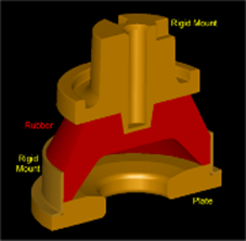
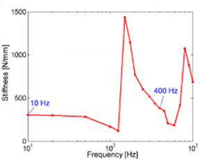
Hydromount analysis using ADINA FEA/ CFD / FSI (courtesy Dr Heck Engineering & Consulting) |

|
10Hz Excitation |
|
40Hz Excitation |
|
ADINA CFD analysis of Exhaust manifold of a Volvo Penta 6-cylinder D6 diesel engine |
|
The animation shows a particle trace in the exhaust manifold of a Volvo Penta 6-cylinder D6 diesel engine. The results were obtained using ADINA’s Shear Stress Transport (SST) turbulence model.
All inlets have prescribed velocity and prescribed turbulence quantities, k and ω. There are 586,120 FCBI-C elements (~3.5 million equations) in the model.
The SST turbulence model exploits the benefits of the k-ω model in the sub- and log-layer and it switches to the standard k-ε model in the wake region of the boundary layer and in the free shear layers. The main benefit of the SST model is improved accuracy of results in the modeling of flows with adverse pressure gradients or pressure-induced separation. |
|
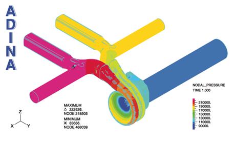
ADINA FEA / CFD / FSI Fully Coupled analysis of Exhaust manifold |
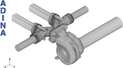
|
Mesh used and (right) fluid pressure plot |
|
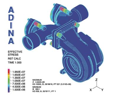
Von Mises stress plot and (left) velocity vectors at different planes in manifold |
|
A particular capability used here, with the meshes used, is the automatic coupling of the temperature between totally different meshes. The model contains a total of about 5 million elements. For the fluid the k-omega turbulence model is used. The Re, Pe and Pr numbers are Re = 0.74 x 10⁵, Pe = 0.54 x 10⁵, Pr = 0.73. |
|
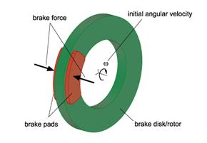
Thermo-Mechanical Coupled Analysis of an Automotive Disk Brake |
|
Unlike in most brake analyses, the rotor deceleration was not prescribed in this model. Instead, the rotor was given an initial angular velocity corresponding to a vehicle speed around 200 km/h, and was augmented with a concentrated mass at its center to account for the vehicle's inertia. A strong braking force was then applied to the brake pads and the rotor deceleration was predicted from the numerical simulation.
The temperature distribution throughout the simulation is shown in the animation. |
|
ADINA FEA / CFD / FSI Door Seal Analysis |
|
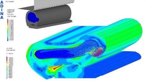
The seal is made up of a rubber material surrounding an air filled cavity. When the seal model is compressed, air flows out through a small orifice. This provides the necessary energy dissipating characteristics of the seal.
The simulation of the seal deformation is a strongly coupled FSI problem where the rubber experiences large strains and contact, and the air cavity experiences a significant change in geometry as air is expelled through the orifices. This requires the use of ADINA’s powerful Arbitrary Lagrangian-Eulerian (ALE) mesh updating formulation. Courtesy of ISKO Engineers. |
|
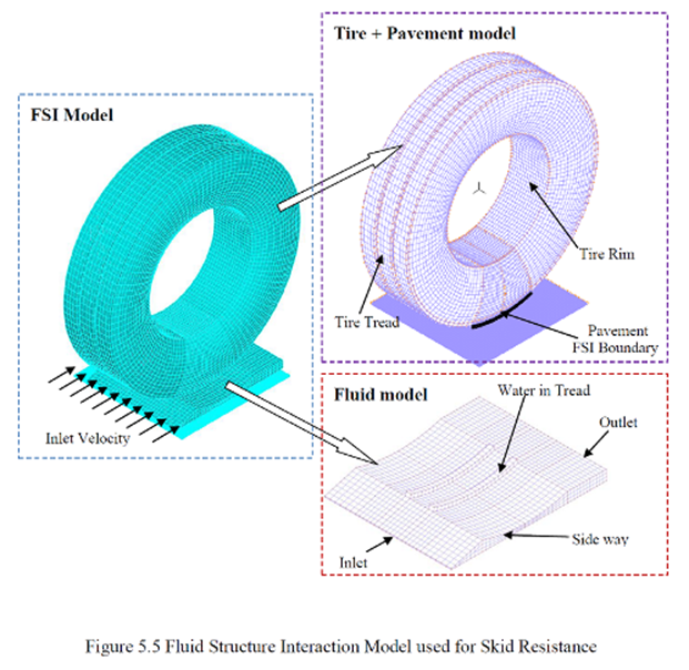
ADINA FEA / CFD / FSI Skid Resistance Analysis |
|
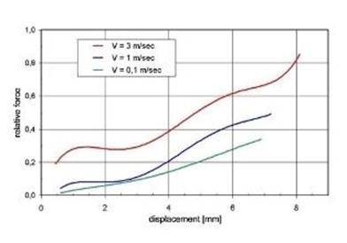
Analytically, compared with hydroplaning simulation, skid resistance is more difficult to model. The main difference in skid resistance simulation is the need for considering the interaction between tyre and pavement.
It was found that that the predicted values agree well with the experimental data
Courtesy of Skid Resistance and Hydroplaning Analysis of Rib Truck Tires, Cao Changyong; N.U.S.; Dec 2010 |
|
ADINA Crush Analysis of Ford Winstar |

|
Tel: +44 (0)121 703 9236 or e-mail: info@pdslimited.com © Copyright Product Development Services Ltd. All rights reserved 2012 |

|
INDUSTRIES |
|