
|
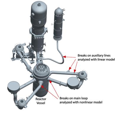
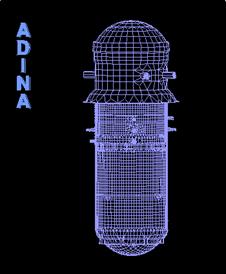
Subject to one of the tightest regulatory standards, nuclear reactors not only should withstand all the environmental effects (e.g., earthquake, wind, etc.) but also should survive potential accidents (pipe breaks, internal explosions, etc.) without leading to leakage of the radioactive materials. This presents a challenge both from the FEA and the design points of view. |
|
The FEA study was conducted by Onsala Ingenjörsbyrå (Onsala Engineering AB, Sweden) which performed the work under a contract from Ringhals AB. Figure above shows the nuclear reactor considered. |
|
The 3D fully coupled FEA / CFD / FSI analysis given here was performed by a Nuclear Power Station using ADINA.
The animation shown depicts the velocity and pressure values during failure of the main steam pipe of a boiling water nuclear reactor.
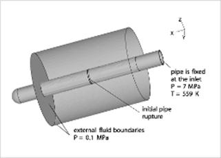
The geometry as shown is a section of the complete pipe.
The fluid domain is composed of the region inside and outside the pipe. The vapor is modeled as a high-speed compressible flow. The pipe is modeled as an elastic isotropic material.
The pressure within the pipe is initially at 7 MPa and the steam temperature is 559 K. Outside the pipe, the pressure is initially at 0.1 MPa. After the pipe breaks, the steam flows out of the pipe causing a sudden drop in pressure that propagates rapidly in both directions along the pipe. These results are used to assess the integrity of the pipe upstream and downstream. The time history of the pressure wave propagation into the reactor pressure vessel is also useful. |


|
Tel: +44 (0)121 703 9236 or e-mail: info@pdslimited.com © Copyright Product Development Services Ltd. All rights reserved 2012 |
|
Study of Pipe Break in a Nuclear Reactor |
|
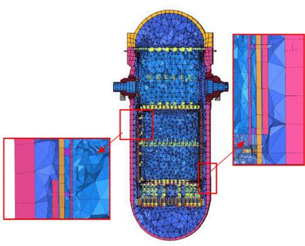
Part of the FEA mesh consisting of solid, structural and fluid elements used to model the reactor vessel |
|
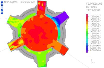
Pressure plot in section of reactor vessel |
|
With the results of the FEA, Onsala engineers were able to predict the structural response of the reactor vessel due to the pipe break (figure above) as well as the maximum bolt forces. |
|
FSI Analysis of a Breaking Pipe |
|
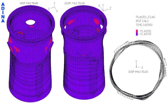
These 3 FEA diagrams are from a FSI analysis of a Forsmark nuclear power plant. These results are courtesy of Forsmarks Kraftgrupp AB, Sweden. Mesh used had about 65000 nodes, consisting of shells, beams and fluid elements. |
|
Core shroud — dynamic stress intensity Pm |
|
Diagram above shows Blowdown experiment in a nuclear reactor Courtesy Onsala Engineering AB, Sweden |
|
INDUSTRIES |
|